Installation dimensions
Installation dimensions: O-Ring seals
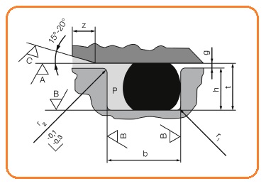
t – the depth of canal
b – width of the canal
g – sealing area
P – pressure
A – surface of the opposite side
B – surface groove
C – surface of the mounting corner
z – length of installation corner
| Diameter material d2 |
Radial seat O-ring | Axial seat O-ring | Radius r1 | Length of installation corner z |
|||
| Depth of canal t | Width of the canal b | Depth of canal t + 0,1 0 |
Width of the canal b + 0,25 0 |
||||
| dynamic hydraulics +0,05 0 |
static
+0,05 |
b +0,05 0 |
|||||
| 1,00 | 0,75 | 0,70 | 1,58 | 0,70 | 1,90 | 0,30 | 0,62 |
| 1,50 | 1,15 | 1,05 | 2,19 | 1,10 | 2,80 | 0,30 | 0,92 |
| 1,78 | 1,40 | 1,30 | 2,53 | 1,30 | 3,20 | 0,30 | 1,10 |
| 2,00 | 1,60 | 1,50 | 2,78 | 1,50 | 3,40 | 0,30 | 1,15 |
| 2,50 | 2,00 | 1,90 | 3,37 | 1,90 | 3,90 | 0,30 | 1,43 |
| 2,62 | 2,10 | 2,00 | 3,51 | 2,00 | 4,00 | 0,30 | 1,50 |
| 3,00 | 2,40 | 2,30 | 3,98 | 2,30 | 4,60 | 0,60 | 1,53 |
| 3,53 | 2,80 | 2,70 | 4,67 | 2,70 | 5,30 | 0,60 | 1,80 |
| 4,00 | 3,30 | 3,10 | 5,23 | 3,10 | 6,00 | 0,60 | 2,03 |
| 4,50 | 3,80 | 3,50 | 5,90 | 3,50 | 6,50 | 0,60 | 2,28 |
| 5,00 | 4,30 | 3,90 | 6,48 | 3,90 | 7,40 | 0,60 | 2,53 |
| 5,33 | 4,60 | 4,20 | 6,86 | 4,20 | 7,60 | 0,60 | 2,70 |
| 5,50 | 4,80 | 4,40 | 7,05 | 4,40 | 7,60 | 1,00 | 2,83 |
| 6,00 | 5,20 | 4,80 | 7,59 | 4,80 | 8,00 | 1,00 | 3,09 |
| 6,50 | 5,60 | 5,30 | 8,17 | 5,30 | 8,40 | 1,00 | 3,35 |
| 6,99 | 6,00 | 5,80 | 8,68 | 5,70 | 8,70 | 1,00 | 3,60 |
| 7,50 | 6,50 | 6,30 | 9,29 | 6,20 | 9,50 | 1,00 | 3,86 |
| 8,00 | 7,00 | 6,80 | 9,88 | 6,70 | 9,80 | 1,00 | 4,12 |
| 9,00 | 7,90 | 7,70 | 11,14 | 7,60 | 11,10 | 1,00 | 4,64 |
| 10,00 | 8,80 | 8,60 | 12,38 | 8,60 | 12,20 | 1,00 | 5,15 |
All measurements are in millimeters.
Please note that the values given in the table are intended as approximate guidelines. Users are advised to check these values for each specific situation (eg. By re-testing). The temperature at the time of use and conditions for fitting can lead to deviations from the values listed above.